 Centre Frequency: 700 Hz
Bandwidth: 200 Hz
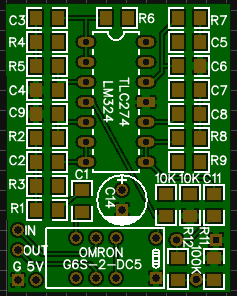
DC Power: 5VDC
GAIN: Up to 20dB via R11 and R12 + trimpot.
Resistors 1206 SMD:
- R1 33k
- R2 33k
- R3 1M
- R4 47k
- R5 47k
- R6 36k
- R7 36k
- R8 10k
- R9 750k
- R11 100K
- R12 100K
- Note the 2 extra 10 K resistors, theses are additions in rev .02 board to bias the circuit.
Capacitors 1206 SMD:
- C1 0.1u 104
- C2 47n 473
- C3 36n 363 (33n + 3n3 stacked)
- C4 1n 102
- C5 39n 393 (33n + 5n6 + 390p stacked)
- C6 1n 102
- C7 2n2 222
- C8 2n2 222
- C9
0.1u 104NOTE this should be 1n (102) - C11 0.1u 104
- C14 220u Electrolytic
Other:
- IC TLC274 / LM324
- Relay OMRON G6S-2-DC5
- 200K/100k trimpot
R11 and R12 are optional to parallel the 200k trimpot to make it a logarithmic 100k.
Or just use a linear 100k pot.
Use a switch connected to 5V to turn on the filter.
This powers the opamp and switches the relay feeding the audio into the circuit.
When off the relay just passes the audio straight through unfiltered
Hi Nick,
ReplyDeleteI saw you also copied this schematic of the Hipemite CW Filter and made a board with EasyEda. I also did that but mine filter doesn't work at all. I checked the schematic several times and can't find a fault. So I'm wondering if the schematic I copied from Four States, doesn't have a fault. The board I made, I want to use it to do CW via the computer and an audio interface. Didn't you had problems with it, maybe you have another version of it. I would be glad if you could help me with this problem. 73 from Roel Bolt, Apeldoorn, the Netherlands. PAS3RWG
rwg.bolt at gmail dot com
Hi Nick, I would be pleased if you could mail me your schematic. Maybe it's different as the one I have. The components in your list however are the same, but maybe something different in the connections! Thanks 73
ReplyDeleteHi Nick, one more question, in your description you mention "Note the 2 extra 10 K resistors, these are additions in rev .02 board to bias the circuit." Where are these resistors in the circuitry? Do you have a schematic of rev.02 ?
ReplyDelete